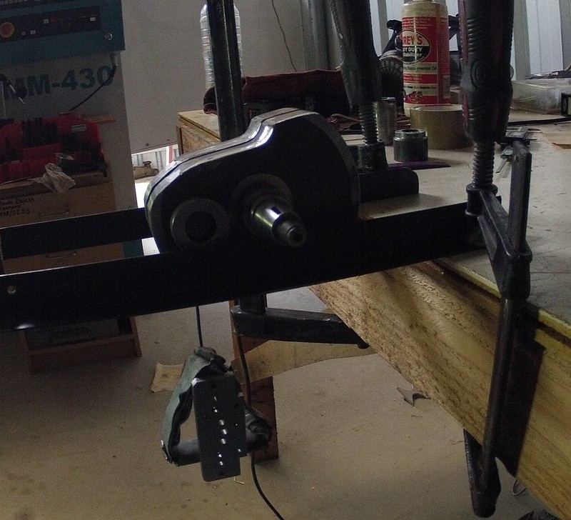
Balancing an 80mm 650 crank

Husaberg

Help Support Husaberg:

This site may earn a commission from merchant affiliate links, including eBay, Amazon, and others.
Back on the scales, the piston is 270g and the rings 13g.

Here's a few pics of the piston,

[attachment=2:h0u2vnju]piston base.jpg[/attachment:h0u2vnju]

[attachment=1:h0u2vnju]piston side.jpg[/attachment:h0u2vnju]

[attachment=0:h0u2vnju]piston top.jpg[/attachment:h0u2vnju]

And even got the pics to show :cheers:
 

Attachments

  • piston base.jpg
    piston base.jpg
    31.5 KB
  • piston side.jpg
    piston side.jpg
    27.6 KB
  • piston top.jpg
    piston top.jpg
    22.8 KB
I'd have gone for the taller and I guess heavier piston and got the squish right. those 2002s are miles away. look at the dished piston. it needn't weigh a helluva lot more...

regards

Taffy
 
Taffy said:
I'd have gone for the taller and I guess heavier piston and got the squish right. those 2002s are miles away. look at the dished piston. it needn't weigh a helluva lot more...

regards

Taffy


I'm just measuring what's in there, not changing anything that doesn't need changing.

Carl
 
plumbbob said:
Taffy said:
I'd have gone for the taller and I guess heavier piston and got the squish right. those 2002s are miles away. look at the dished piston. it needn't weigh a helluva lot more...

regards

Taffy


I'm just measuring what's in there, not changing anything that doesn't need changing.

Carl

Interesting ! perhaps you can measure the squish height for us all ? It's not difficult.
 
berglsmerg said:
Interesting ! perhaps you can measure the squish height for us all ? It's not difficult.


Can it be measured with the engine in bits?

Carl
 
with the piston on the rod, in the liner, in the left case you can be reasonably close. with both cases together then you're good. in a knackered state...no. get the P & B and little end done first.

anyway, even a tall piston still misses the head by 2mm. this is with the 134mm C to C rod coded '164'.

regards

Taffy
 
Crank Butchering

machining with carbide was painfully slow so i used a thin 5" cutoff disc $3.50 and all done in about 15 min. gotta love grinders

12673936814_642922060d_c.jpg


Dummy pin with a nice centre pivot to hang the bob weight, lead weight triangle substitues makes up the total weight of the real pin + rod + bearing, the bit of metal with holes in it is the bob weight

12673433995_f60a2937f8_c.jpg


12673913354_9295ba001c_c.jpg


lighter rod.. a massive 30% lighter and its stronger as well ! I had hoped for more than 20gm but I chickened out with the grinder :oops:

12673928794_e21e1d5b3d_c.jpg


Plumbob, Weed has let me know his 644 at 70% BF works fine and reckons 10% either side would also be OK
 
Cheers Bushie,

I'm going to bolt it all up with the cb out (spacer instead) and see how it goes with my balance factor.

Carl
 
the old "fat" cranks of weeds and mine,

no problems with the welded weights about 200 hrs on mine .. weed even more I think.

so if you don't have a spare $800 to spend on Mallory or have fancy carbide drills a little preheat and some stainless weights work very well.

12685660695_7cabf20a01_c.jpg


12685801563_ee2b3507a6_o.jpg


various lightened KTM RFS cranks, GWR DJH and others

12685661495_d478b7b220_o.jpg


12685798603_c1533e321a_o.jpg


12685802193_5e0f2de555_c.jpg


12685660995_a498940f0d_c.jpg


12685660265_1c381d717f_c.jpg


12686133124_c26bc8e624_c.jpg


12686132764_4eedd8cb30_c.jpg


12685659765_75bf2ccb0a_c.jpg


12685799793_2ed67bbcf8_c.jpg


12686131824_877033b7d5_o.jpg


12686131614_34f0d74483_o.jpg


12685800043_04e9d49467_c.jpg


12685658385_c8f2b2a914_c.jpg


12685658285_e8683f8753_c.jpg


and mine again, not quite as radical but not much work either and no expensive mallory

12673433995_f60a2937f8_c.jpg
 
I wish I had a lathe. I do have access to one but since the owner is a sub contractor to Öhlins I'm not so sure they'd let me use it! :lol:
 
lathes are amazing machines, It always spins me out how people where making reasonably accurate lathes and mills in the 1700s by hand, and with those machines they produced better ones... and so it went on until today when you can buy a computer controlled "mill" robot with less than 0.001mm resolution for less than the typical operators yearly salary 8O 8O

drive side pressed in and welded (more on how to weld later)

12761564105_2ff17098ac_c.jpg


press the other side on 10mm or so and get both halves parallel by measuring in 3 spots and pressing more as needed

12761709493_83eb01eb1b_c.jpg


12762008074_cec3b5a92d_c.jpg


12761557665_4016414016_c.jpg


if you need to open it up somewhere use wedges

12761542215_761cf15679_c.jpg


when its parallel check for twist between centres, mark the high spot on either side

12762003804_a053258503_c.jpg


12761555345_3d336ce621_c.jpg


12761689623_ce368b9d91_c.jpg


take the crank out hold it by your rod and hit the un-welded (free) flywheel to twist it into the right place

recheck parallel and look for high spots again

when it not twisted your high spots will line up

12761701113_89417e4347_c.jpg


happy with the twist, press it together. use a feeler gauge to help stop at 0.1mm bigger rod axial play than you want to have at the end. im going for 0.7mm so i set it at 0.8mm here

12762000954_72f3520e31_c.jpg
 
welding the pin

the ignition side weld needs to be flush to clear the bearing and the bearing mount in the case

so grind a fillet out

12761698643_71aed5c379_c.jpg


make sure the crank is as true as possible at this point then put 4 tacks in

make sure the crank isn't twisted before you tack it. after tacking you can't correct the twist

12761697693_450a2d6ef6_c.jpg


preheat to 150C then use the weld shrinkage to keep the crank true as you weld, fill in a bit at a time and check how its going between centres

after the welding starts is is pointless to use force (press or wedges) to true the crank, you have to use the weld shrinkage only.

before checking the crank each time take a hammer and tap the crank around a bit to let it settle

I use a TIG welder with a foot pedal ER7OS2 filler rod and pulsed DC

12761997874_7e7576dc22_c.jpg


welds on this one pulled the flywheel up.. sometimes they go down ..need to be aware :oops:

so if one side needs to come up (or down depending on its mood) just go over it again, nice big fillet with good penetration .. doesn't look very pretty :D

12761695723_bb24226ec7_c.jpg


I keep a bucket of diesel ready and if I reckon its getting too hot i drop it in there for a while, you want to minimize the blueing if possible

ground down to clear the bearing and case

12761687743_65f13d115d_c.jpg


12761693343_a319fba20a_c.jpg
 
me too :D :D

everytime i do this something new comes up, this crank wanted to open up with the weld shrinkage usually they close up. :?

maybe something to do with the different type of timing marks i drew.. opposite behavior of the rockets
 
So one thing that I've been mulling over - what if adjustment is needed later? Or if the conrod needs replacement?

Re. adjustment/change afterwards: Someone posted a picture of a cracked weld on a crank here - do you just grind out the weld and start over?

And if you need a new conrod? The same, or could the conrod be sawed or ground off without damaging the crankshaft? and then replaced with a conrod with a bolted big end? (correct term?) Or are the welds ground out like when you're preparing for the weld job on the ignition side?
 
Hi tourist

yes you are on the right track

I grind the welds out of the ignition side then press the flyweel inwards so the rod axial play is zero

the end of the pin now protrudes a bit more so I grind the sharp edge off and then press it out as normal

same the other side if the pin needs replacing

or yes if the rod and pin are toast just cut the pin through the rod, much easier

my other crank in the 700 is on its 3rd pin

Cheers
Bushie
 

Register CTA

Register on Husaberg Forum! This sidebar will go away, and you will see fewer ads.

Recent Discussions

Recent Discussions

Back
Top