This site may earn a commission from merchant affiliate links, including eBay, Amazon, and others.

FE 501 2001: Timing Gear & Cam Timing confirmation please

Joined Mar 2022
6 Posts | 1+
UK
Hello,

I am looking for advice on whether it is safe/wise to put the lid back on my Berg with the following Timing Gear and Cam (55) position at TDC.
Try as I will, I cannot get the single dot to line up between the two lower dots and have the cam lobes "parallel" to the cylinder head (sitting at 1 and 11 o'clock).
I am fairly new to this and any guidance would be much appreciated.
Please see pictures for details.


Reason for opening her up. Engine was running rough, a lot of engine vibration at coasting and acceleration.
Wanted to first double check all "timings" & valve clearances before moving on to jetting.

Many thanks.


PS: source of info: Rebuilding Husaberg Motorcycle Engines Guide
 

Attachments

  • Husa01.png
    Husa01.png
    4.5 MB
  • Husa02.png
    Husa02.png
    5.2 MB
Last edited:
so she is on line 3, the lobes are beautiful but the gears are wrong. then it is perfect. the gear teeth often don't line up and you get an 'L'.

Cheers

Taffy
 
Thanks Taffy.

Looks like I may have found a possible solution by browsing though your Media Gallery and reading through some older threads:
- OK I need help with this cam chain thing
- valves or timing problem


I have the Timing Gear dots nicely lined up at TDC and the flywheel mark is also in order.
Cam timing will have to wait a while, as I lost bits of my pencil down the hatch.🤣

Removing the cylinder head to retrieve my lost property, I noticed what looks like rust forming (img: 03_PistonHead).
Is this normal and can it be avoided?
What would be the best way of removing it?
 

Attachments

  • 01_TimingGearTDC.png
    01_TimingGearTDC.png
    5.4 MB
  • 02_FlywheelTDC.png
    02_FlywheelTDC.png
    5 MB
  • 03_PistonHead.png
    03_PistonHead.png
    4.8 MB
Last edited:
Thanks Taffy.

Looks like I may have found a possible solution by browsing though your Media Gallery and reading through some older threads:
- OK I need help with this cam chain thing
- valves or timing problem


I have the Timing Gear dots nicely lined up at TDC and the flywheel mark is also in order.
Cam timing will have to wait a while, as I lost bits of my pencil down the hatch.🤣

Removing the cylinder head to retrieve my lost property, I noticed what looks like rust forming (img: 03_PistonHead).
Is this normal and can it be avoided?
What would be the best way of removing it?
Regarding timing:

With some models the primary gear may be moved quite a lot on the crank (where the woodruff key sits)-resulting in a seemingly off timing.

Regarding rust:

It can´t be avoided...head gaskets consist of steel and composite material.
Iron plus water plus oxygen equals iron oxide. ;)
 
Vieln Dank Jojo.
That is valuable info regarding the primary gear and timing, good to know. 👍

Never seen rust in this area before on other bikes I have but you are right, chemisrty cannot be avoided.

Waiting on a new head gasket before finishing setting the timing.
Alas, there is now no more confusion as to where TDC is. 😂
 
  • Like
Reactions: jojo09
UPDATE 01: TIMING GEARS & FLYWHEEL MARK [SOLVED]


I have found that the piston head is at TDC for several degrees when turning/rotating the flywheel/ timing gears (2-dot gear fits the crankshaft
and the 1-dot gear the intermediate shaft). Lets break it down into three 'stages'.

Stage 1: as the piston head reaches TDC (dots on timing gears make a 'L' shape)
Stage 2. while it is at TDC (dots on timing gears are one-between-two)
Stage 3. just before it leaves TDC (dots on timing gears make a 'reverse-L' shape)

For each 'stage' the flywheel and thus the flywheel mark will be at a slightly different position (degrees). However, the piston head remains at TDC as
the flywheel and timing gears continue rotating and therefore the dots on the timing gears seem not to line up perfectly even though you are positive
that you are at TDC. You might find that you are either at 'stage 1' or 'stage 3'.


Images will be uploaded soon.
Update on cam timing to follow once top end has been reassembled
 
Last edited:
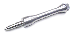
tdctool.jpg

Top Dead Center (TDC) Tools

To get absolute TDC use the Dead Stop Method:

Insert the piston stopper into the spark plug hole and turn the crank slowly until it stops the piston. Mark the flywheel and the case. Then spin the motor the other way around until it stops and mark just the case where the flywheel mark is. Now split the difference and mark between the two marks on the case. This is true TDC.
 
Thanks.
Brilliant tool, Makes the job a hell of a lot easier.

My cylinder head is removed. Ended up doing it the long way.
 
UPDATE 01: TIMING GEARS & FLYWHEEL MARK [SOLVED]


I have found that the piston head is at TDC for several degrees when turning/rotating the flywheel/ timing gears (2-dot gear fits the crankshaft
and the 1-dot gear the intermediate shaft). Lets break it down into three 'stages'.

Stage 1: as the piston head reaches TDC (dots on timing gears make a 'L' shape)
Stage 2. while it is at TDC (dots on timing gears are one-between-two)
Stage 3. just before it leaves TDC (dots on timing gears make a 'reverse-L' shape)

For each 'stage' the flywheel and thus the flywheel mark will be at a slightly different position (degrees). However, the piston head remains at TDC as
the flywheel and timing gears continue rotating and therefore the dots on the timing gears seem not to line up perfectly even though you are positive
that you are at TDC. You might find that you are either at 'stage 1' or 'stage 3'.

My process:
I aligned the dots on the timing gears; 1-dot between 2-dots.
With the the cylinder head removed, I set the piston to TDC (01_FindingTDC.jpg).
I noticed that TDC is between 'stage 1' and 'stage 3' which corresponds to the dots alignment on the timing gears.
I marked the flywheel at 'stage 1' and 'stage 3' (02_Stage1.jpg & 04_Stage3.jpg). Between those two was true TDC (03_Stage2.jpg).

In short. My true TDC is at 3,5/4mm to the right of the two original flywheel marks (05_TrueTDC.jpg). I vaguely recall Taffy mentioning in a post or via phone, that a fairly accurate
estimate for true TDC can be found 4ish mm to the right of the original two flywheel marks. Not quite equidistant. Pretty spot on.

If you find this useful, great. If I am mistaken somewhere, let me know. 👍
 

Attachments

  • 01_FindingTDC.jpg
    01_FindingTDC.jpg
    1.3 MB
  • 02_Stage1.jpg
    02_Stage1.jpg
    1.1 MB
  • 03_Stage2.jpg
    03_Stage2.jpg
    1,016.6 KB
  • 04_Stage3.jpg
    04_Stage3.jpg
    998.2 KB
  • 05_True TDC.jpg
    05_True TDC.jpg
    1,002.6 KB
Last edited:

Register CTA

Register on Husaberg Forum! This sidebar will go away, and you will see fewer ads.

Recent Discussions

Recent Discussions