SEM KOKUSAN Conversion

Husaberg

Help Support Husaberg:

This site may earn a commission from merchant affiliate links, including eBay, Amazon, and others.
Joined
Jun 13, 2007
Messages
3,871
Location
south east WA Australia
has been done by a few people

I like this one http://husaberg.org/electrical/15015-kokusan-husaberg.html#p129331
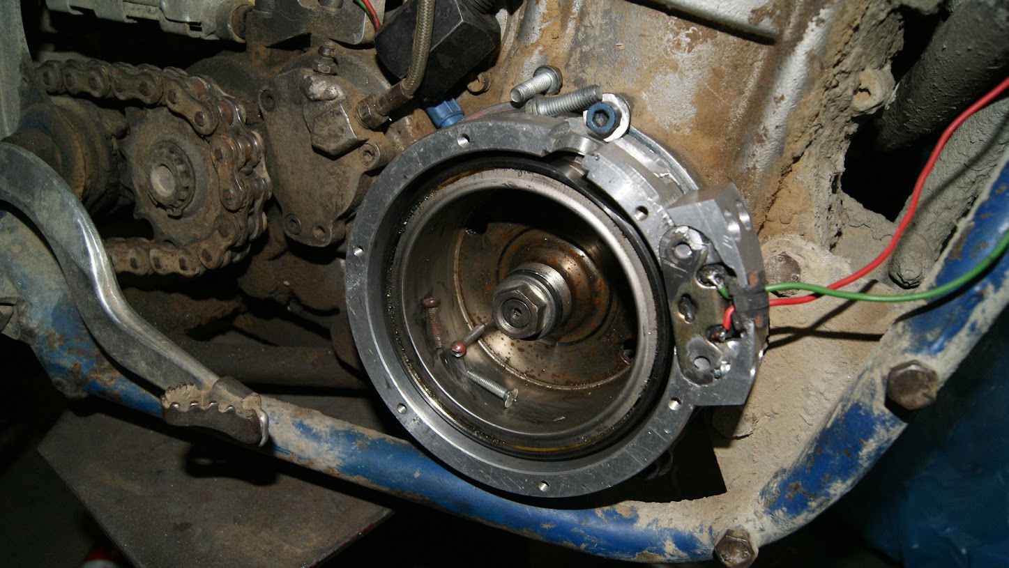
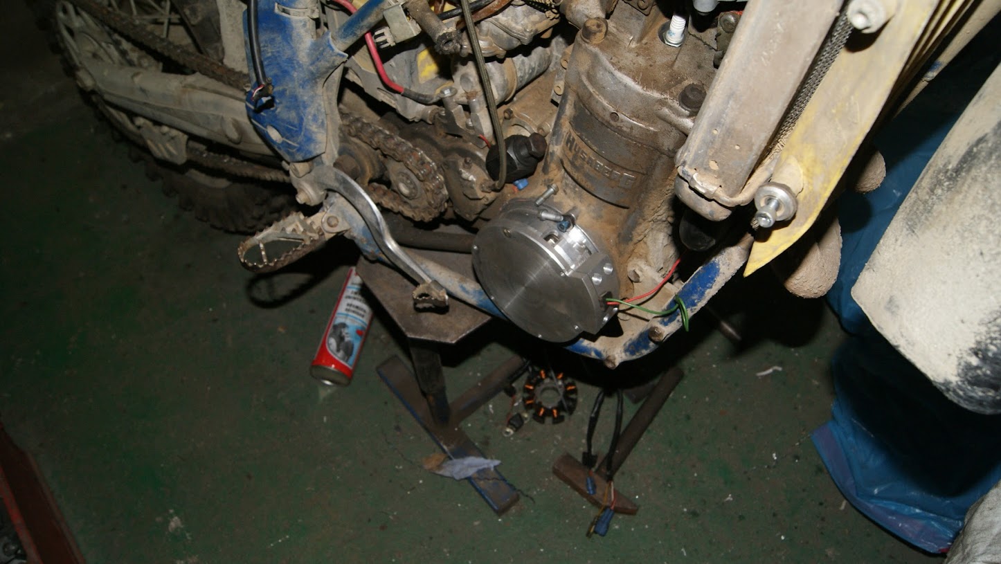
DSC01818.JPG


LAymlstLqtolL7R3wgkxzUiR6SZUjzwiktmbQpvZkg8=w1447-h815-no


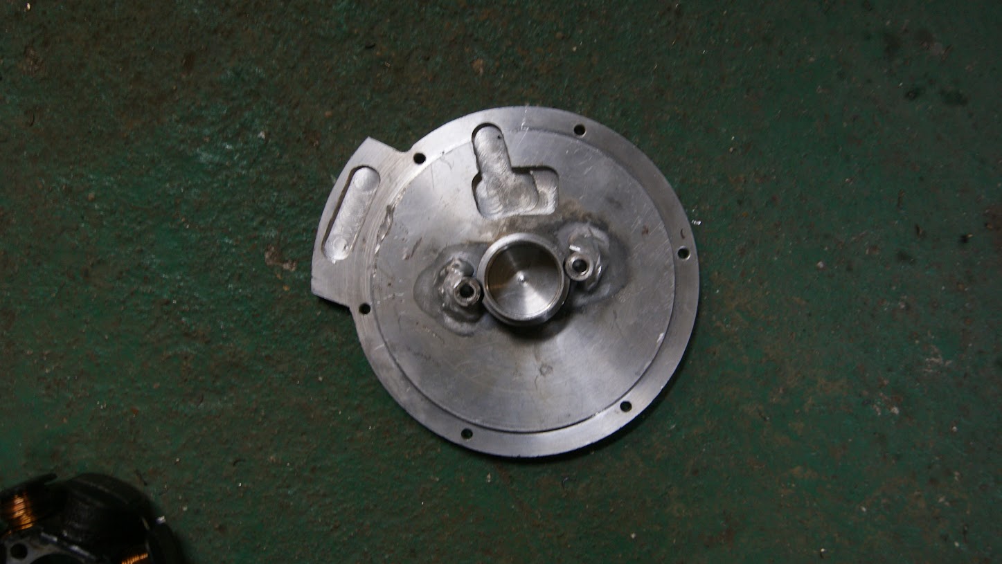
DSC01820.JPG


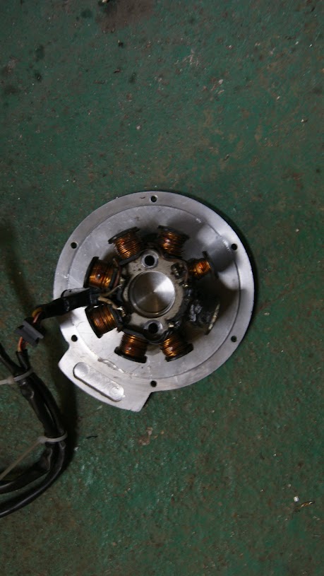
DSC01821.JPG


more threads HRBmans pics are in the gallery so they don't show up

http://husaberg.org/electrical/15345-cross-ref-ktm-berg-kokusan.html#p131904

http://husaberg.org/electrical/17355-sem-kokosan-rebuild-possible.html

more results via google https://www.google.com.au/search?ne...armpp...0...1.1.45.serp..17.1.221.Mo3fRJVH4G8
 
I'm using the husaberg Kokusan ignition system to put in 2002 650 cases simply because that's what i have to work with.

the easiest way IMHO would be with the FC stator and flywheel as they will easily allow the pulse coil to fit inside the 02 ign cavity, the FE flywheel is bigger and pushes the pulse coil out into the cavity wall

FC flywheel 80039005100 $200 USD and stator 80039004100 $160

this build of mine is made up of my spare parts so im using the big flywheel

I put both 02 and the newer cases in the mill and clocked all the important bits then put the pulse coil in the model, see PDF

on these 02 cases the required centreline of the pulse coil is nearly aligned with the drain plug. if you were to punch a mark on the centre of the drain plug it will be only out by approx 1.5 deg advanced. FWIW if you wanted to rectify that just make another punch mark 2.8mm higher up on the plug.

more pics when bit of metal start flying around
 

Attachments

  • 550 layout for kokusan ignition.pdf
    119.1 KB
Last edited:
I like how you spend your time playing with the important stuff and dont bother wasting time with stuff like cleaning, ha ha! Always good to see somebody having a go at solving problems like this. Will be very handy when parts are non existant and mixing and matching will keep these beasts alive!
 
Hi Bushie

You starting this job, has gave me the momentum to start my !

Last time I've put my hand in to this, I had come to the conclusion that I had to change the position of the metal strip of the flywheel more out, so if I had to changed it, why not putting it in the position that I wanted ? Not to the front of the bike, but to the sprocket side (back) ?

What do you think about that ?

Also can you change the colour of the drawing ? It's very hard to read the green. Thanks

:cool:
ZAGA
 
that's a good idea actually to relocate the strip Zaga

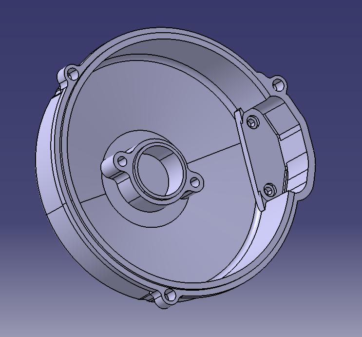
to put the pulse coil in the same location as for the new cases is a bit tricky as it interferes with one of the cover bolts and one of the case bolts on the 02 cases.

one cover mount hole is covered by the pulse coil and one case bolt is hidden under the cover so I will weld a 1/2 nut to the head of the case bolt and use this for the third bolt thread

I have one model done with the pulse coil mounted upside down in the cover

now trying to decide weather to order a big chunk of aluminum and turn it into swarf pillow stuffing for Dr_C or make a mold and try a carbon cover.

im going to be running the coils in oil so i prefer aluminum ATM.

OK Zaga no more green lines :D

14148677977_a0ab17cf04_c.jpg


14148539590_3bbc982055_o.jpg
 
Hi Bushie

I can see your CAD master, I should, but I don't have a clue how to use it :eek:

The dimensions of your cover might be bit different that I want, because you will be using ne FC flywheel, but anyway, could you post another pdf without the lines in green ? Thanks

Just 2 more ideas that I previously had, first I don't know if I can get the timing exactly right, so I thought of using one back plate for the stator and pulser coil that can be adjusted, something like the 2 stroke KTM. I don't know how the my CDI will behave, so before I do something rigid and be sorry after, I think I should do something that can be a bit tuned. Another member Paul, that knows a lot about ignitions, told me to stay bellow 40º advance, to be safe maybe between 32º - 36º, so a tuneable solution would be wise.
Other idea is to make one hole in the cover so you can check timing with a strobe.

Why are you going to use oil, they seem to last on the KTM's dry, why are you going for that trouble ?

Cheers
ZAGA
 
When I'm talking about a back plate, here are some examples
 

Attachments

  • KTM200002-1.jpg
    KTM200002-1.jpg
    81.8 KB
  • DSCF5040.jpg
    DSCF5040.jpg
    48.6 KB
Hi Zaga

the oil will be in there because I am boring out the main bearing tunnel to take a sleeve for a 20mm wide spherical roller and there is not much room for the seal.

Im using the FE flywheel not the FC so the models dimensions should be usable for you, when its working i'll create some ISO drawings for you to go off, and yes I can redo the first one.

I like your ideas about having a means for altering the timing, this build for me is just a cheap trailbike to ride around in the bush with some old mates of mine I know with big beer guts so i'll be happy with replicating the oem kokusan timing.

this shows where the half nut goes


14336276315_e5a1e06569_c.jpg
 
Last edited:
here you go Zaga

layout without green

not sure which dimensions you are interested in, let me know.

the top of the cases at the head gasket is setup parallel to the X axis

14313450146_88e73811a3_b.jpg
 
Sorry mate, but what are this for ?
 

Attachments

  • 14336276315_e5a1e06569_c_22.jpg
    14336276315_e5a1e06569_c_22.jpg
    50 KB
they are my new flux capacitators ZAGA :D

the large one is the boss with the gearbox input shaft in

the small one is the oil drainplug

Don't need to model the whole case yet
 
OK mate :)

But what flywheel are you using ?
I have one kokusan complete from the KTM 400/525, and on TDC my pickup coil will have to be in the same position of the photos from berg_501, and yours is positioned in the opposite side (near the drain plug).

Cheers
ZAGA
 
OK

And what is the clearance you are planning to leave between the pickup coil and the flywheel or the metal strip ?

Cheers
ZAGA
 
Hi Zaga

the oem setup uses 1mm clearance so i will replicate that

quick pic of clocking the 02 ignition bits

14382709923_6684655f31_z.jpg
 
I now have the FC stator weighs 505grms vs 835 for the FE/FS.
The trailtech stator should fit inside dia being 60mm, and is available
on its own for US$145.
Mounting hole pitch is 46mm vs 41mm so an adapter would be necessary,
and some mods to the cover.
I have a spare cover, Have I got time....:)

S-8360A.jpg
 
On closer examination the OD of the trailtech stator, 60mm is about the same as the ID of the FC flywheel needs to be around 1mm per side clearance.
Could possibly turn the OD of the stator down:(
 
sounds interesting spanner

there is usually plenty of room to grind the core laminates down if needed, I think it would work
 
Hi Bushie

Thanks for the info.

Also about the flywheel, did you had to change anything to fit perfectly in the crank journal ?

Cheers
ZAGA
 

Register CTA

Register on Husaberg Forum! This sidebar will go away, and you will see fewer ads.

Recent Discussions

Recent Discussions

Back
Top